This is part 3 of Jorges magnificent Catalina. Pictures of the constructions can be found in Part 1 and Part 2
When I was detailing my 1/48 Catalina kit, I realized that much of its interior would be hidden forever once the fuselages halves were closed.
In the meantime I was continuously receiving, from several modellers, more info about its interior, and I was really enjoying that detailing process - so more details were to be added. It was a pity to hide all that.
Several friends suggested keeping the fuselages halves unassembled; or alternatively, placing some strategically located removable panels in order to view the interior. Since I wanted to model a complete aircraft, the first option was ruled out; being not a fan of the second option (nor was the kit conceived for it), the second was discarded too.
So I chose the traditional solution that many modellers had adopted in this case - adding some lights in its interior.
In a model of this size, placing LED's in its interior and hiding its circuit wires should not pose a problem at all.
My real problem was to find a place to hide its on-off switch, and I found that the best solution was to use a rotary electrical switch and connect it to the propeller. By just turning one of the propellers, I would turn the LED's on or off. The size of the engine nacelle would be capable to hide the switch; the batteries could be hidden in the other nacelle. So that was the initial idea.
Since the batteries available today are very small (when compared to those of the seventies), in all probability I could build a unit containing both the power cells and switch, and place it inside one of the nacelles. But I still had to find an appropriately small sized switch.
It was Geraldo, an electronic technician and friend of mine, which suggested the use of a reed switch, a magnetic action switch. Therefore, a magnet eccentrically attached to the propeller shaft would turn the lights on or off. That was exactly what I needed! Now I could build the switch and the battery case in a single unit, and place it inside of one of the nacelles. All I had to do was to build the plastic structure to carry the electric array.
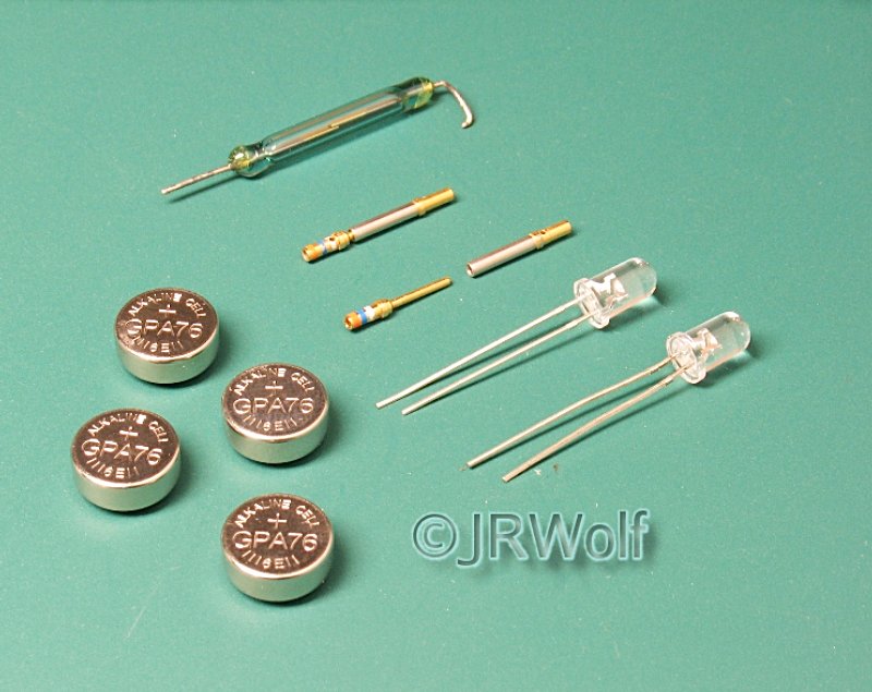
He then gave me a reed switch, two LED's, a few male and female pins, a magnet and some length of wire to work with. I purchased four batteries cells to power the system. All these items are shown below.
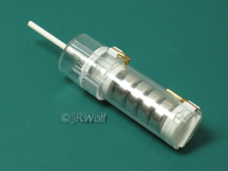
He also supplied me with several discarded electronic plastic lids; the two that I chose to scratchbuild the self-contained power and switch unit are shown below.
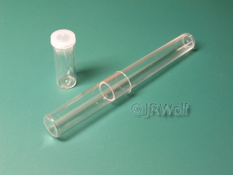
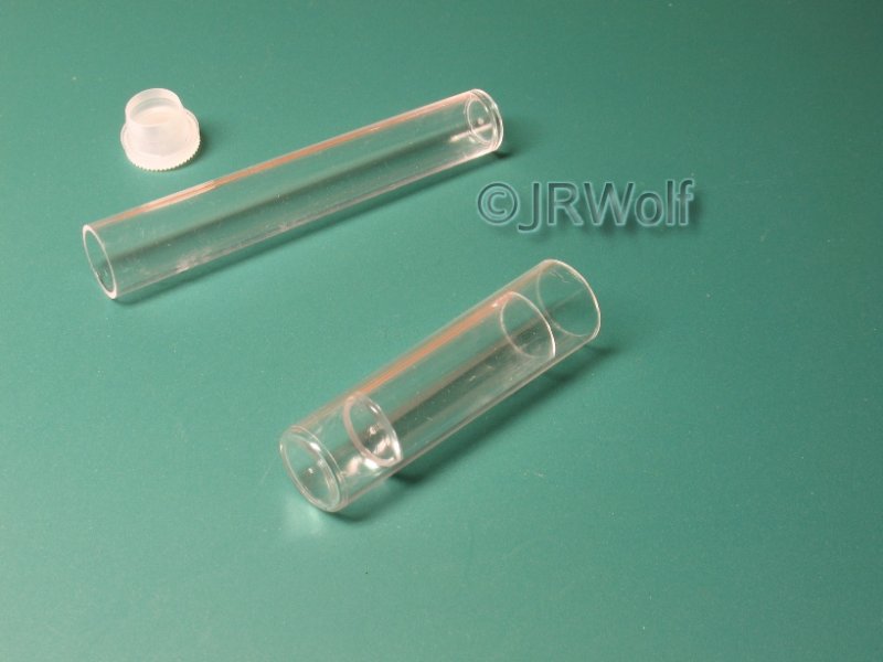
I chose two lids so that one could be inserted tightly inside the other as shown, and proceeded to prepare them appropriately. Due to the brittle nature of the clear plastic, some cracks appeared during my work, however.
The outside diameter of the larger lid is 16.5 mm; on the smaller one, 14.7 mm. It must be noted that these lids are not exactly cylindrical; in fact, they are conical, with a very subtle angle.
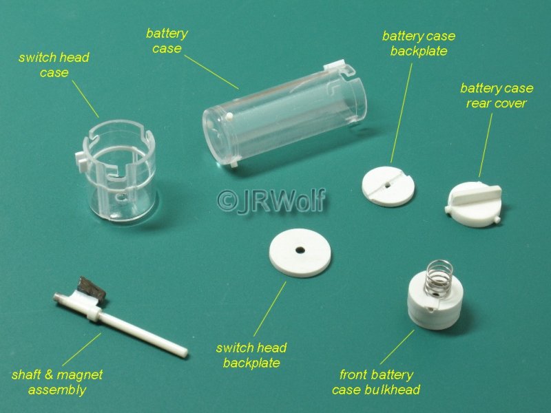
I added three plastic locking pins and 'L' shaped grooves to the switch head and battery cases in order to lock them firmly after joining. Then I built the shaft, backplates and bulkheads too, as shown I the picture below.
A small spring was included in the front battery case bulkhead, in order to compress the battery cells against the positive and negative pole pins. This bulkhead has a small slot, where the positive pole pin will be inserted later, which of course must make contact with the spring.
Accordingly, I carved a channel in the battery case backplate, in order to guide the negative pole pin that will be inserted later.
The magnet is already eccentrically glued to its shaft. Some graphite powder was dusted over the axle in order to minimize friction.
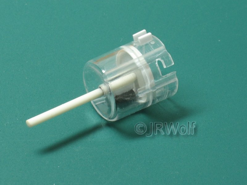
The assembled switch head is shown below. I added some grooves externally in order to install the reed switch and the front (positive) pole pin connector later.
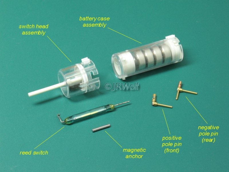
The complete switch head and battery case sub-assemblies are shown in the following picture. The negative and positive pole pins were made from male and female pins, and soldered as shown.
A magnetic anchor (a steel nail minus its head) was placed over the switch head in the opposite side of the reed switch, in order to prevent turning the circuit on by accident, thus avoiding wasting power from the batteries and extending the life of the LED's.
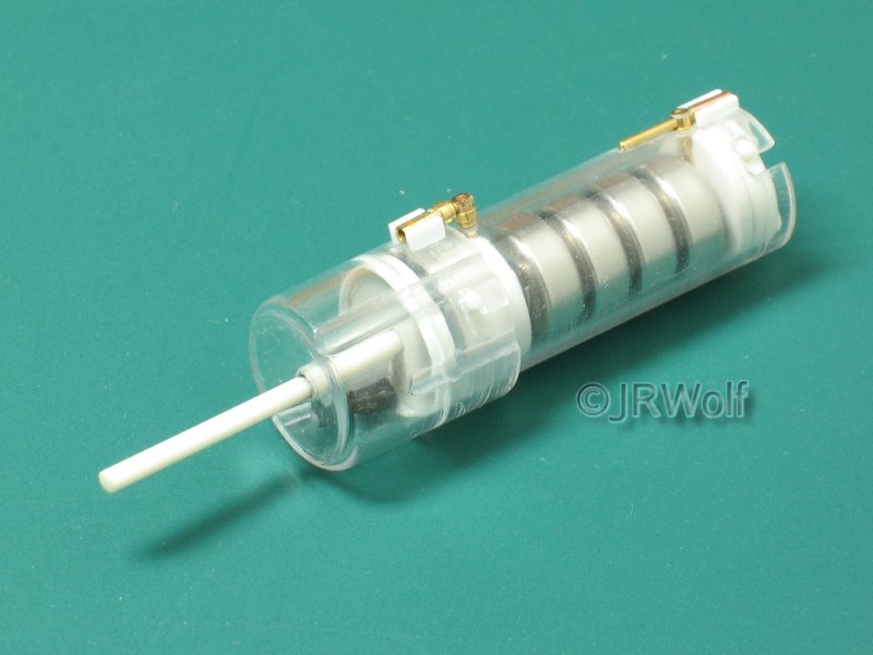
The switch head and battery case sub-assemblies are now joined together, with the positive and negative pole pins installed, as shown in the following pictures. The overall length of the complete unit, minus its shaft, is 52.1 mm long.
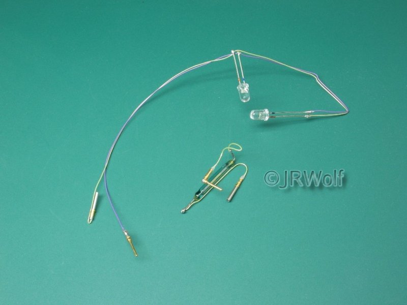
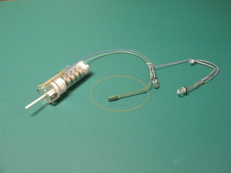
The electronic items (reed switch, LED's, pins and wire) were appropriately soldered in sub-assemblies, as shown in the picture below. The reed switch sub-assembly will be glued later to the external surface of the switch head assembly.
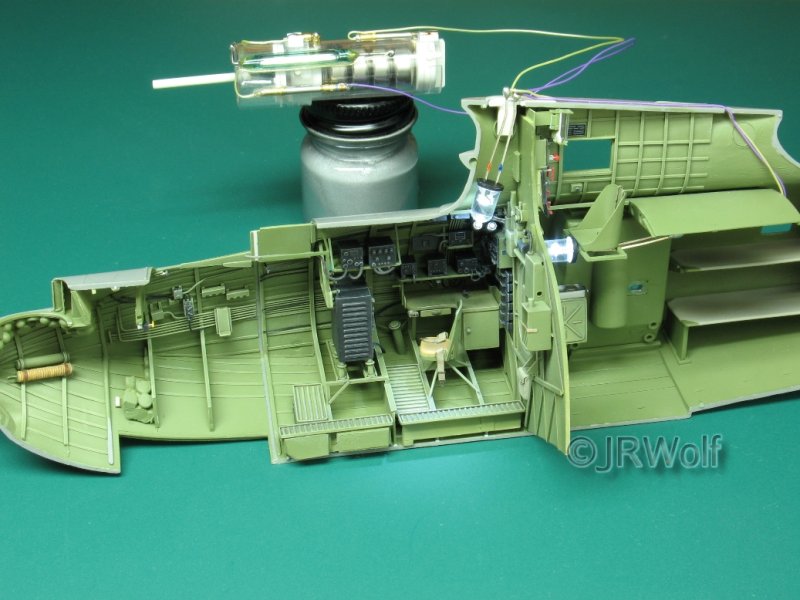
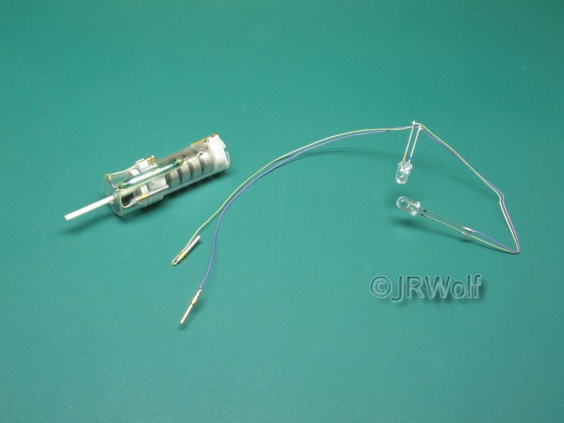
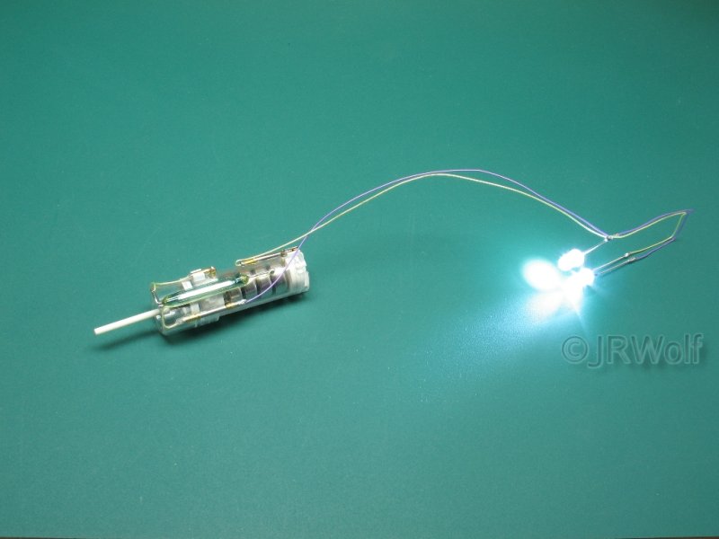
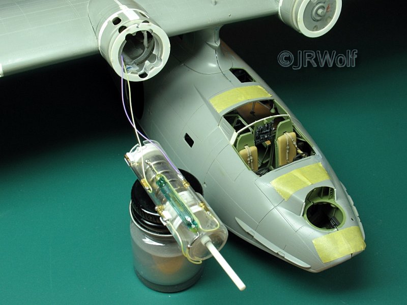
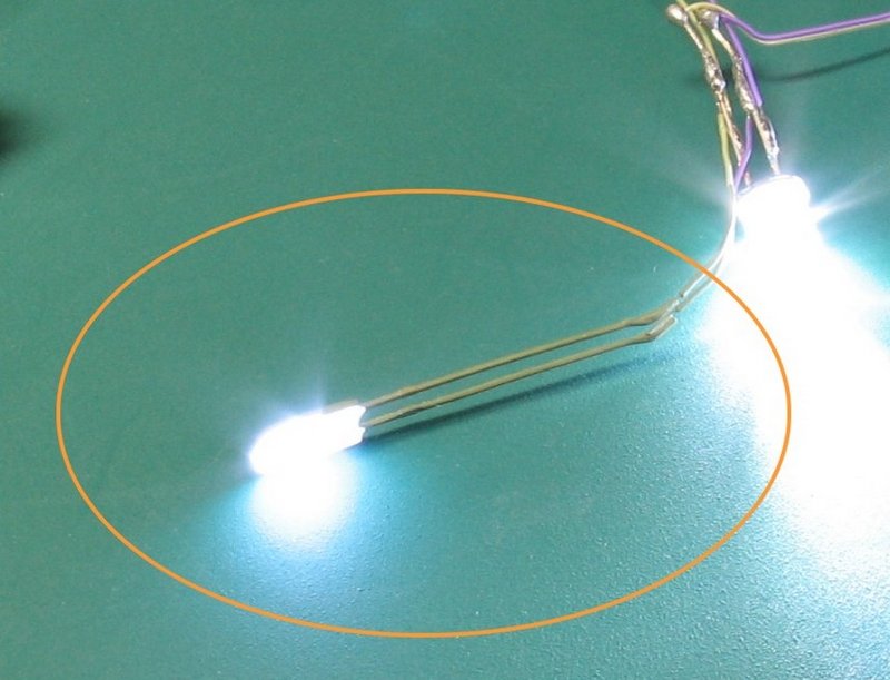
The following pictures show the complete unit with the electronic items already glued to the switch head, at left with the circuit aside; and at right, with everything assembled and the LED's on.
The LED circuit was then glued in the fuselage, as shown below. The wires will be inserted through the wing, to the starboard nacelle, where its connecting pins will join the power unit.
In the last picture, the power unit is fully hidden in the nacelle, with the cowling installed in its place.
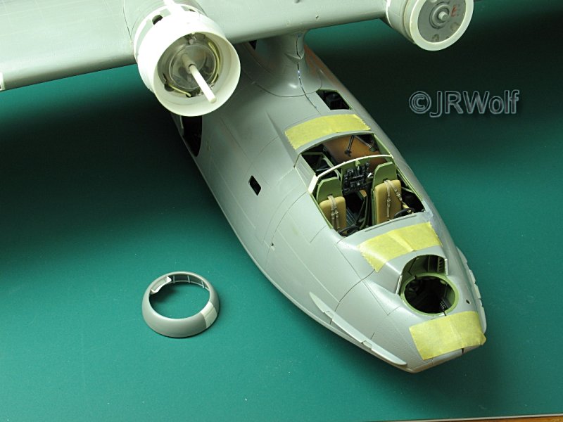
The propeller and cowling will not be glued; they are just snapped in place and may be removed later in order to replace the batteries, when required. The entire power unit can be disassembled, if necessary.
So, here is a way to display the interior of my model and hide its on-off switch. Unfortunately, some areas of the interior will still be hidden, but I can live with that; at least, I photographed all the scratch building process.
Please feel free to contact me at jrwolf000@yahoo.com.br to ask any modelling related questions; any constructive critics are welcome too.
By the way, any electronic related questions can be sent to rangel6691@yahoo.com.br, where my friend Geraldo will gladly answer them.
I would like to thank my friend Geraldo for his kind help.
I must confess to you that the success of those three articles really surprised me, since there are so many excellent models in the web today (and more detailed than mine). At that time, even the editor of the a Magazine contacted me offering the possibility to write an article to them! And there was more... last year, I was sent to Paris (France) for a few days. One evening, after the work, I decided to go to the store Euromaquette. Once there, I recognized the clerk and we talked about our hobby. When I told him about my Catalina articles in the IPMS Deutschland website, he recalled them immediately, as well as his customer friends that were there!
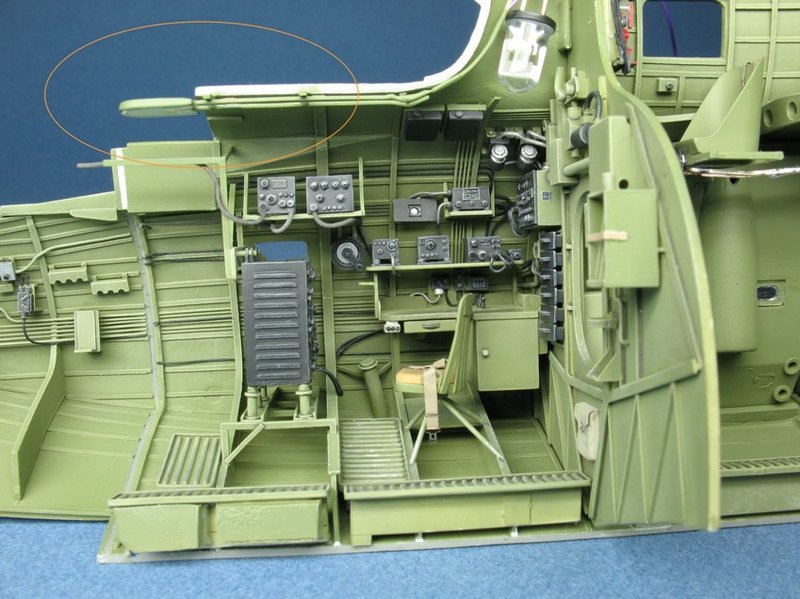
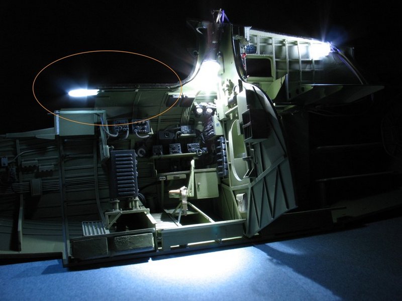
I added two more LED lights in its interior (now there are four); one of them was sanded in order to leave it flat (the bulb is not glass; it is resin and can be easily reshaped at will), as shown in the attached pictures. This is especially useful to place and hide them in the ceiling, as is the case here.
By the way, the fuselage halves of my Catalina are now closed and the rear fuselage had been corrected. I had to cut it several times; but at least, it is feasible!
Good luck and happy modelling from Brazil!
Jorge Roberto Wolf